

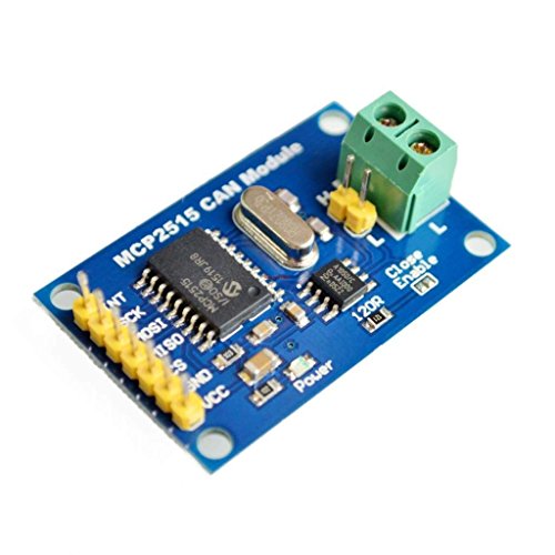
- Supports CAN V2.0B specification, the communication speed 1Mb/s.
- 5V DC power supply module, SPI interface protocol control.
- Working current: 5mA (1 microamp standby current. Except the power indicator).
- 0 to 8-byte data field. With standard frame, expand the frame and remote frame.
- 120 ohm termination resistors. With impedance matching, ensures the drive capacity, long-distance data transmission against signal radiation.
-
Information
-
Twitter
-
Pinterest
-
Youtube
-
Facebook
Johnny Banks
Bring IoT to your car
The modules shipped quickly. They were in perfect condition. HiLetGo sent emails to see if I had any questions about installing it. My first move was to connect two of them in a send-receive master/slave. I apologize for not having the wires all neat, but it works. I am using two NodeMCUs, each equipped with an OLED module (via I2C). I used the CAN-BUS Shield library, and the send/receive Blink sketches. modified to use the OLED modules. Some of you might be asking how I hooked modules that require 5V to an MCU with 3.3V output. Simple: connect the VCC pins on the module to the Vin on the MCU, making sure you supply the MCU 5V through the USB port. My next step will be to take the receiver setup and coonect it to an ODB-II jack, to read data from my car.
Waren Doll
Works well with a small mod for Esp32
Cut the lead line on the bottom. Soldered a wire on the resistor. Was able to use this with esp32 3.3v, so long as I had 5v power and 3.3v to the extra wire!