


- The chip model: CP2102; There is the way to guide you to use the new version: The command you needed to use is: esptool.py --baud 115200 --port /dev/tty.SLAB_USBtoUART write_flash -fs 32m -ff 80m --flash_mode dio 0x00000 boot_v1.7.bin 0x1000 user1.bin 0x37c000 esp_init_data_default.bin 0x37e000 blank.bin The important part is “—flash mode dio” https://github.com/espressif/esptool/wiki/SPI-Flash-Modes;
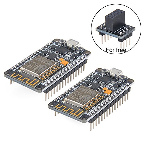
- Firmware link: https://github.com/nodemcu/nodemcu-firmware; Data download access to the website: http://www.nodemcu.com; Test Video: https://www.youtube.com/watch?v=Gh_pgqjfeQc; Makerfocus nRF24L01+ and ESP8266 ESP-01 Breadboard Breakout Adapter Board is come for free, it can compatible with "nRF24L01+ " and ESP8266 ESP-01. If you need more information about it, pls refer to: https://www.amazon.com/dp/B01N5AK6E1;
- ESP8266 is a highly integrated chip designed for the needs of a new connected world. It offers a complete and self-contained Wi-Fi networking solution, allowing it to either host the application or to offload all Wi-Fi networking functions from another application processor.
- ESP8266 has powerful on-board processing and storage capabilities that allow it to be integrated with the sensors and other application specific devices through its GPIOs with minimal development up-front and minimal loading during runtime. Its high degree of on-chip integration allows for minimal external circuitry, and the entire solution, including front-end module, is designed to occupy minimal PCB area;
- We Have a Strong After-sales Service Team: As long as you have any questions about the product, we will resolve your issue immediately if received your email, your satisfactory purchase experience is our greatest hope! How to email us? Plz click “MakerFocus” and click “Ask a question” to email us! Looking forward to your consultation!
-
Information
-
Twitter
-
Pinterest
-
Youtube
-
Facebook
Toni M Johnston
Makerfocus is the best and these boards are also amazing!!
At first I had trouble with neither board working but I contacted makerfocus which has the best support in the world and sent me my replacements asap and they work amazingly have quit a bit of reach and do everything I wanted them to do! I plan on buying more and if your in the market for these buy as many as you can and if they are DOA (dead on arrival) just contact them with a few pics of the boards top side and a video showing them that they dont work and they will replace what ever broke one you have! The esp 8266 WiFi chip gets a Lil hot after a while but it doent matter because it doesn't get super duper hot. Has 8mb storage and works with arduino just look up how to use with arduino, set it up and boom they work. Dont use Linux because its a hassle to get working but on windows it works just fine.
Robert Victor Moore
Quality control issues
So NodeMCU boards themselves are great and I highly recommend them to anyone looking to get into hobbyist electronics/maker movement/IoT. However, when I ordered this pack I was disappointed that one of the boards doesn't work properly. It appears that the microUSB jack isn't attached properly, so it works intermittently only if torqued to weird angles. So it's effectively unusable, and I can't repair it without a solder reflow oven. The board that does work is great, though. EDIT: Seller contacted me and quickly issued a refund for the defective board. Again, the board that does work is great, so hopefully the bad one was a fluke.
Karl Wilbanks
A great module for use with the Arduino IDE
I ordered two of these models. Both are running very well. I am using one as a wireless web server to retrieve time from a server to set a nixie tube clock. I can also control the clock features from a Web page via a 2-wire I2C interface. The other unit is wired to a Neopixel RGB led ring with three wires. The module retrieves local weather conditions and displays an LED animation that corresponds to the weather conditions. The 3.3 voltvregulator seems to supply plenty of current to the module. I have had no dropouts or other WIFI issues. The Arduino IDE uses the GPIO numbers on the BOTTOM of the board, not the data pin designations on the top, which are for the NodeMCU environment. The bright blue built-in LED is connected to Arduino D2 or just "2". There is a second, smaller LED at Arduino D16 or just "16". Remember to use a bidirectional level converter board if interfacing to 5 volt logic, as the inputs are NOT 5-volt tolerant. I2C requires a bidirectional converter on both the SCL and SDA lines. The "EN" pin shuts down the ESP8266 chip when grounded, but not the 3.3 volt regulator. The Huzzah boards use the pin to shut down the regulator as well. Although not a bug in the board, the ESP8266 does not have separate code and data FLASH memory areas like Atmega-based Arduino. Loading a new Arduino sketch does not seem to erase certain memory areas, such as where the WIFI credentials are stored. To clear memory completely, I had to download a utility from the chip manufacturer and flash a blank 1megabyte fill file to 4 blocks to fully blank the chip. That's the only way I found to clear previously set WIFI setting back to their factory state.
Chauntal Pike
They work great
I've ordered one of these items (so two boards) so far from this seller and both boards seem to work great. We'll see if this continues if I order more; At another point in time I ordered from a different seller, and the first 2 boards were great, but the next two didn't work due to incorrect soldering and missing components! My only complaint here is that some of the headers aren't soldered in perfectly straight, so I have to bend them slightly to fit into a breadboard or PCB socket. UPDATE: I've now ordered 11 of these (so 22 boards, mostly for a class at a local maker space) and they all work fine during initial testing. No quality control issues here:-) The headers appear straight on the latest batch, and each pair comes in a small cardboard box so the packaging is reasonable too.
Willam Tonelli
Ready, Set...Automate!
So far, these little wonders seem the remote-sensing mensch among the SOC solutions; low power-consumption or otherwise. Application firmware can be written, compiled and uploaded from ProjectIO, Arduino, Visual Studio and possibly other IDEs. You can be up and working in a few minutes by adding the ESP8266 repository to Arduino's 'board repository' (in File -> Preferences...), then installing it via the 'Board Manager'. This installs the the most recent toolchain and examples for all wireless functionality, diagnostics and integration of commonly used sensors. The examples are a bit more than 'bare-bones' but certainly aren't production-ready (fi, the 'complex web server' fetches a IP address but doesn't refresh the address when the lease expires). It was able to maintain its network connection during a 24 hour stress-test while performing I/O on nearly all ports and never even felt warm to the touch. The firmware can also be flashed over the air (OTA / wirelessly) which fills out its feature set and puts it on par with all others in the field-ready wireless remote-sensing MCU class of solutions. Looking forward to future versions.
Jeta Jeta
Great boards from a great company!
These little boards are great for any wifi connected project. These Makerfocus boards have been solid and reliable once up and running. They come with the AT firmware, and to flash them, all you need is a USB cable. Just make sure that you set the DIO flag when flashing them. I actually had a defective board sent to me, however the speed and quality of Makerfocus' customer service was bar none. They rectified the issue in very impressive time. I am very happy that I did business with them
Su San
Great boards!! Once you figure them out...
These boards are an incredible value!! Having the integrated Wifi makes building IOT projects extremely easy to complete. There are a couple of issues that I struggled with at first: - The pin numbers are a little confusing, when programming using the Arduino IDE insert this code at the beginning of your sketch to convert from the Dx pin numbers printed on the board to pin numbers that Arduino recognizes. //ESP 8266 PIN OUTS #define D0 16 #define D1 5 // I2C Bus SCL (clock) #define D2 4 // I2C Bus SDA (data) #define D3 0 #define D4 2 // Same as "LED_BUILTIN", but inverted logic #define D5 14 // SPI Bus SCK (clock) #define D6 12 // SPI Bus MISO #define D7 13 // SPI Bus MOSI #define D8 15 // SPI Bus SS (CS) #define D9 3 // RX0 (Serial console) #define D10 1 // TX0 (Serial console) - In addition, the V3 boards are too wide to use on a standard width breadboard. If you use two breadboards side by side you can solve this problem and have plenty of space for your projects. I have attached a photo that shows how I did it.
Frankie Keller
Great ESP8266 NodeMCU board
This NodeMCU board is of very good quality. See attached pictures. It comes with all that is necessary to program the onboard ESP8266, no need to get a USB to TTL adapter or fumbling for 3.3V power supplies. All you need is a mini USB cable. I tried it on my PC (Windows 10) and Mac (MacOS Sierra). In Windows 10, it works fine without any additional driver. On the MacOS, make sure to install the latest drivers before plugging in, otherwise it will crash your Mac! The drivers for MacOS can be found here: [...]. The onboard buttons make it really easy to program. Press and hold Flash, press and release Reset while leaving Flash button pressed and launch programming from your PC or Mac application. I think this would be a great IoT platform for beginners and advanced users alike. I plan to use it for developing and testing ESP8266 code, before deploying to a bare bones ESP8266 board when done for the final product.
Janelle Williams
Good module, the right feature set for me
This NodeMcu esp-8266 module has been my go to development and often deployment version of the ESP series. For me, it's the right tradeoff between cost, power, complexity, and ease of use. You can save a little with a raw 12e module or a board that lacks the USB<>serial, but it's often simply not worth it for the extra effort unless you were making a mass produced product. Wifi is most of the power consumption anyway, and the ability to trivially program and re-program (even an already deployed device you find a bug in) via USB is a real time saver vs using an external USB<>Serial cable and providing headers for that.
PM A Rodriguez
Great for Learning and Protyping ESP8266
I purchased this pair of boards and, overall, I am very pleased with my purchase. They arrived well packaged with the boards in individually sealed, anti-static bags. Inside each bag, the board was pressed into a foam sheet to protect the pins from damage. I have worked a lot with static sensitive electronic devices, and these were well packaged for optimum protection. Although I haven’t done extensive testing with the boards yet, I did verify that both are functional. They came with the NodeMCU “AT” firmware loaded, but I use them with the Arduino environment and load ‘sketches’ to them. There is no documentation provided with the boards, but I think that most of the buyers of these boards are pretty adept at finding documents on the internet. Using Windows 10 Home edition, the Silicon Labs CP210x USB driver loaded automatically. I think Win10 downloaded the driver from the internet because the search & loading process took about 60 seconds. Once the driver is loaded, connection time to the PC is nearly immediate upon plugging into the USB port. A little experimentation with different micro-USB cables confirmed that cable length does matter. Although the module receives power and will function on a longer cable, getting the device recognized as a COM device with a cable longer than 3-feet (1 meter) is not reliable. Some of my 6-foot cables worked, and some did not. I recommend cables of 3-ft or less for programming and debugging. I only tested the COM port speed at 115.2Kbps and 230.4Kbps; both worked fine. I did not try to load sketches faster than 115.2Kbps. I was not finding any information on which “board” to select in the Arduino environment, so I chose “NodeMCU 1.0 (ESP-12E Module)” and it seems to work perfectly. After loading programs that generate web pages to control I/O pins, both boards connected quickly with my home network. In addition to securely connecting to my home network, I also have the boards set to simultaneously act as Wi-Fi “access points”. The default access point name is “AI-THINKER_” followed by the last six characters of the device’s MAC address. If you let your PC connect to it, the module will provide your PC with an IP address (yep, these things have onboard DHCP service) and you can access your web page(s) by pointing your web browser to 192.168.4.1. I have not looked into whether the access point name or IP are changeable, but the IP settings for the module’s connection to my home network are easily changeable. One of things that I especially like about these particular boards is that all of the pins are clearly labeled on both sides of the circuit board. This makes prototyping much easier as you are not constantly looking at a pinout diagram and then counting pins on the board to make sure you are wiring to the correct pin. I like that the board has “FLASH” and “RST” buttons, and they are clearly labeled. All labeling is silk screened onto the circuit board, and appears to be quite durable. For those who have not used ESP-12E modules, there is a blue LED next to the antenna on the actual ESP-12E. This LED is primarily there as an indicator that the board is communicating serially with the PC, so you should see it flashing when you are downloading a program or using serial communication with the board. This LED is actually connected to GPIO2, so if you configure that pin to be an output then you can also turn the LED ‘ON’ and ‘OFF’ with your program. It is a great way to flash status codes from your prototype program. I know this review is long, but it is the type of information I look for when deciding whether or not to buy something I am considering buying.