

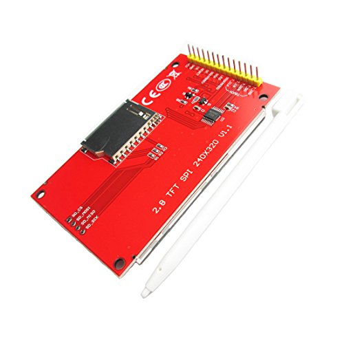
- Driver element: a-Si TFT active matrix
- Resolution (dots): 240RGB*320Dots
- Viewing Direction: 6 o’clock
- Pixel arrangement: RGB vertical stripe
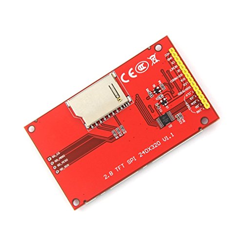
- With PCB plate (including power supply IC, SD), compatible with 5110 interface
-
Information
-
Twitter
-
Pinterest
-
Youtube
-
Facebook
Hareem Sania
Works with Teensy 3.2 or Arduino - here's how:
I love these displays and use them on all my projects. I've bought about 8 so far and can get them to work with either Teensy 3.2 or an Arduino Nano. For operation with a Teensy 3.2 1. use the from the PJRC--and this lib is very fast connect directly 2. for touch use "UTouch.h" 3. for SD I use 4. no level shifters needed 5. you may need to solder J1 (I do on all my displays) 4. if you want to use SD, remove the resistors R1, R2, R3 and solder 0 ohm resistors For operation with Auduino Nano 1. use the 2. for touch use "UTouch.h" 3. for SD I have yet to get an SD to work with graphics due to not enough memory 4. no level shifters needed 5. you WILL need to solder J1 (I do on all my displays) EDIT as of 12/29/2019 Usage with Arduino connect as usual but power your Arduino with 3.3 volts (just connect 3.3 to the 5V pin on the arduino). Alternatively you can put a 1K series resistor on all pins to drop the voltage going to the unit (and power with 3v3). THESE UNITS WILL NOT WORK IF POWERED WITH 5 AND IF THE SIGNAL LINES ARE 5 VOLTS.
Sarah Sylvester
don't forget to initialize theconstructor with the reset pin
It works well. Initially, I ran into problems with this - all I was getting was a white screen with an Arduino Uno and an Adafruit Feather, and the Adafruit ILI9341 libraries weren't working. I contacted HiLetgo and they were very friendly and helpful and sent me an email with all the schematics I needed. After perusing them for a bit, I realized that this unit is actually a 3.3V unit.. If you're connecting it to an Uno or a Feather, you'll need to buy a bidirectional logic level shifter to convert the SPI pins, DC and RST pins from 5V to 3.3V. Also, when you're using the Adafruit library, don't forget to initialize the constructor with the reset pin, otherwise, you'll have errors at times. Something like: Adafruit_ILI9341 tft = Adafruit_ILI9341(TFT_CS, TFT_DC, TFT_RST); Also, use hardware SPI pins with this unit preferably.
Sharon Lotayo
Nice bright display - easy to get working
Very easy to get working - I added this to an an ESP8266 controller, from HiLetgo to build an alarm clock that is time synchronized to an NTP server. The instructions provided by HiLetgo on Amazon for the ESP8266 https://smile.amazon.com/gp/product/B010N1SPRK got me going very quickly, the only part I had to change was step 3 where it said use: esp8266com_index.json. This URL periodically seems to go off line, and was unavailable when I was setting up, so instead I downloaded the source, and used that locally. I also added an oled display from HiLetgo and ran an example sketch to display wifi networks. The idea is to use the TFT display to show the time, while the oled display will show the alarm time(s). It as very easy to wire up the hardware and get the examples running - now just need to spend some time writing the software. As all three items are running from the 3.3 volt supply, I bridged the J1 connector with a blob of solder, which bypasses the onboard regulator. I started running from an external supply, but the whole thing only seems to be drawing 150mA and the onboard regulator is spec'd at 800mA so now for development I am running it all from the USB power, the regulator is barely warm!
Francisco Peña
They work fine at 3
These are very robust. They work fine at 3.3V and 5V logic. Over SPI with the right microcontroller, I've run these with up to a 60 MHz clock and they still handle it (that was the edge of glitches though in my experience). For what these are, and what they cost they are very nice. The ILI9341 chipset which drives this thing is pretty standard and there's a number of C/C++ libraries which support it. Just be patient, follow the directions, and it should work. There is a touch screen on it, but it is of the resistive variety which means it only detects one point at a time and don't expect miracles from it. Otherwise, I think it is amazing that for this money (and cheaper if you get from China directly) you can get a display like this nowadays.
Stacey Baum
Works great with ESP32
Using this with an ESP32 on hardware SPI pins, with Adafruit libraries, it's 20-50x faster than using the default pinout. Hardware horizontal scrolling in landscape mode works great. It didn't come with any documentation but there is plenty of websites and video tutorials for this display. It's not an IPS display so it looks pale/dark when facing away from the viewer, and I couldn't find a way to manually adjust the contrast with a potentiometer, but there should be a way to do so programmatically on the ILI9341 controller chip if I'm not mistaken.
Competitive Coaching Centre
Not a 5v logic display, 3.3v only.
Item works well with Adafruit's ILI9341 and GFX libraries. NOTE: If you are using this with a 5v device such as an Arduino, be aware that did not work for WITHOUT level shifting to 3.3v logic. I pulled my hair out for a half hour wondering why nothing would display. After using level shifters I got the display to work. You will not need to shift levels with an ESP8266 since it is 3.3v natively.
Serban Vanessa
Works Great
I am using this ILI9341 2.8" display with a Teensy 3.6 using the Teensy 3.x Standard pinout table found on the Teensy website. The display uses an XPT2046 touch controller so ILI9341_t3.h and XPT2046_Touchscreen.h were both needed. I made a modest attempt to change SCK to pin 14 because pin 13 is also the built in LED which I wanted to use. This proved unsuccessful. Without a lot of effort to find out how to switch SCK I wired up a separate LED. Anyway, using the exact 3.x standard wiring this display works perfectly.
Linda Briere
These display modules are bright and readable
These display modules are bright and readable. I used one for an esp8266 based weather station display. You don't have to use the touch screen or sd card functionality if you don't need any of those functions. For my purposes, just display over SPI is fine, and this module works great for that. The header pins are already pre-soldered on, so less work to get started prototyping with jumpers. Overall, it's a fantastic little touch screen / display for Arduino or Raspberry Pi projects.
Paula N Moore
You need a lot of wires and 3.3V
This thing pretty much does everything. Very nice graphics and reasonable touch. For the money, can't be beat. I've only used a logic level shifter to 3.3V with this. Everything works fine when you use it. Pins of interest: CS is Chip Select (user defined) Reset is Reset (user defined) DC is DC (user defined) MOSI is MOSI SCK is the Clock LED ties to VCC (3.3v) MISO is MISO The Touch Screen is simpler The SD Card slot need to have posts soldered Otherwise, very good value. Works great. Use the Adafruit ILI9341 library for the LCD. Use the Adafruit STMPE610 for the touchscreen Use the SD library for the SD card
Tanya Jannat
It is better than I expected
I'm new in Arduino, and my first test project was to drive this LCD with a Wemos Mini Lite. My choice might not the best, but I found these libraries as a good start: For the graphics, I used the "Adafruit-GFX-Library" from github alongside with the "Adafruit_ILI9341" library. For the touch sensing, there are so many libraries, and everyone is endorsing different authors. I found two promising candidates: the "XPT2046_Touchscreen" library from Paul Stoffregen, and the "XPT2046" library from Spiros Papadimitriou. The first one is dead simple. No fancy calibration or complicated algorithms, but it has interrupts. The second one has a calibration and a differential algorithm, but no interrupts. Both are using the regular SPI library, so no direct pin manipulation. (Which is a good point in my opinion.) The SD card is so standard, I just used the SD library from the esp8266 package. Since all the three components use SPI bus, I don't see, why was it necessary to provide independent pins for everything. As a result, my test board looks like a spaghetti. Making my final circuit won't be different. Ouch... Unboxing the LCD gave me a heart attack. When I saw the stylus, I just remembered the old resistive touch screens, where the stylus was the only options due to the bad sensitivity. This guy gave me a nice surprise: It is working fine using just fingers. The resolution is enough for DIY projects, and I did not feel the lack of colors either (there are "only" 65536 of them). The screen's visibility needs a little forward thinking. The default orientation is portrait mode, when the 4 pin for the SD card is on the top. Use this orientation when you plan to use the LCD on a horizontal surface (like a desk), or when you hold it in hand. If you want to put it on a wall, and your eyes are will be above the screen, make it upside-down, because the screen starts loosing visibility if you turn from right angle towards the top just a little bit. If you prefer landscape mode, you can choose either sides, because there is no difference. There is a pretty big range for the viewing angle, although the screen won't be as vivid as in portrait mode. It is still enjoyable, you just won't see the darkest 10-15% of the color spectrum. The only thing I would change is the SD card reader's position. The card itself hangs over the edges by 3/4", so you have two options: use a bigger box to hide it, or accept the fact that the SD card will stick out significantly. Anyway, it is a hardware design they cannot change. At least I assume, because the same LCD panel can be found on different websites, from different vendors. The pricing is also vary. I know that there are cheaper alternatives, but I didn't want to wait 4-5 weeks for my gadgets, and I'm sick and tired of fighting for the warranty overseas. I rather pay few more bucks for the hassle-free delivery and customer service.